Network Cables; How Cable Temperature Impacts Cable Reach
There is nothing more disheartening than making a big investment in something that promises to deliver what you require – only to find out once it is too late that it is not performing according to expectations. What happened? Is the product not adequate? Or is it not being utilised correctly?
Cable Performance Expectations
This scenario holds true with category cable investments as well. A cable that can not fulfil its 100 m channel reach (even though it is marketed as a 100 m cable) can derail network projects, increase costs, cause unplanned downtime and call for lots of troubleshooting (especially if the problem is not obvious right away).
High cable temperatures are sometimes to blame for cables that don’t perform up to the promised 100 m. Cables are rated to transmit data over a certain distance up to a certain temperature. When the cable heats up beyond that point, resistance and insertion loss increase; as a result, the channel reach of the cable often needs to be de-rated in order to perform as needed to transmit data.
Many factors cause cable temperatures to rise:
- Cables installed above operational network equipment
- Power being transmitted through bundled cabling
- Uncontrolled ambient temperatures
- Using the wrong category cabling for the job
- Routing of cables near sources of heat
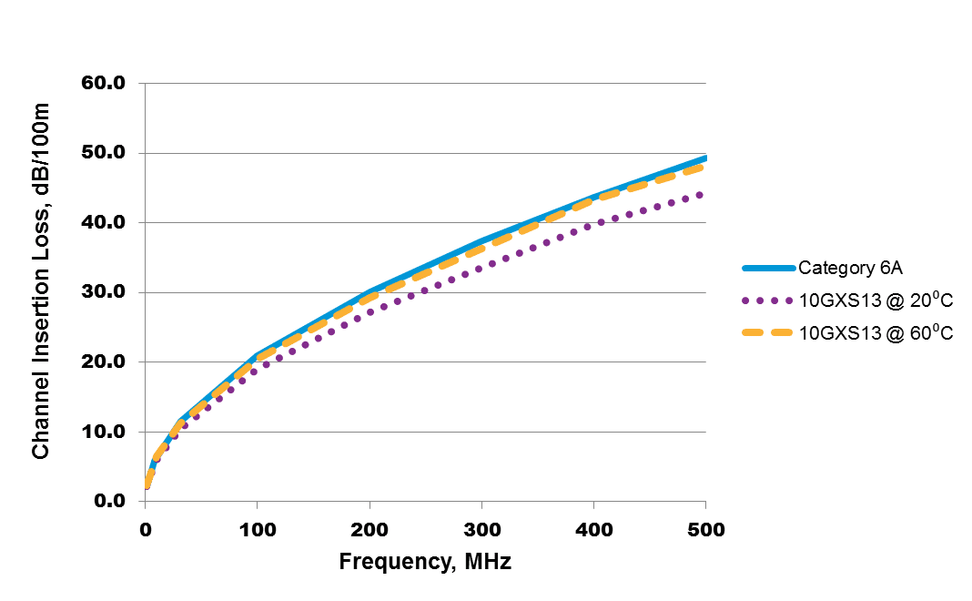
In Power over Ethernet (PoE) cables – which are becoming increasingly popular to support digital buildings and IoT – as power levels increase, so does the current level running through the cable. The amount of heat generated within the cable increases as well. Bundling makes temperatures rise even more; the heat generated by the current passing through the inner cables can’t escape. As temperatures rise, so does cable insertion loss, as pictured below.

Testing the Impacts of Cable Temperature on Reach
To assess this theory, I created a model to test temperature characteristics of different cables. Each cable was placed in an environmental chamber to measure insertion loss with cable temperature change. Data was generated for each cable; changes in insertion loss were recorded as the temperature changed.
The information gathered from these tests was combined with connector and patch cord insertion loss levels in the model below to determine the maximum length that a typical channel could reach while maintaining compliance with channel insertion loss.

This model represents a full 100 m channel with 10 m of patch cords and an initial permanent link length of 90 m. I assumed that the connectors and patch cords were in a controlled environment (at room temperature, and insertion loss is always the same). Permanent links were assumed to be at a higher temperature of 60 degrees C (the same assumption used in ANSI/TIA TSB-184-A, where the ambient temperature is 45 degrees C and temperature rise due to PoE current and cable bundling is 15 degrees C).
Using the data from these tests, I was able to reach the full 100 m length with Belden’s 10GXS, a Category 6A cable. I then modeled Category 6 and Category 5e cables from Belden at that temperature, and wasn’t able to reach the full 100 m. Why? Because the insertion loss of the cable at this temperature exceeded the insertion loss performance requirement.
Read full article


