Single-Pair Ethernet Cabling: Four New Applications

Four New Types of Single-Pair Ethernet Cabling

For years, Ethernet cabling has used four twisted pairs to carry data without worrying about noise in data lines. Recent developments in IEEE 802.3 (Ethernet Working Group) and TIA TR-42(Telecommunications Cabling Systems Engineering Committee) has unveiled four standards projects which may change that; instead of four balanced twisted-pairs cabling, these standards feature a single balanced twisted-pair Ethernet cabling.

Of these four, one will impact enterprise networks the most. We will cover this standard first, and then explain the three other types of single-pair Ethernet cables below.

IoT 1 Gbps Applications: 100 m Reach

2017 Ericsson Mobility Report says that there will be nearly 28 billion connected devices in place globally by 2021 – and more than half of these will be related to Internet of Things (IoT).

With the ability to deliver data at speeds of up to 1G, and PoE power, this standard is intended specifically for IoT applications. Known as ANSI/TIA-568.5, it will provide cable, connector, cord, link and channel specifications for single-pair connectivity in enterprise networks.

This single-pair Ethernet cable may help network professionals connect more devices to their networks as the industry moves toward digital buildings – where all types of systems and devices integrate directly with the enterprise network to capture and communicate data.

Most of the devices used in digital buildings – such as sensors – have minimal power and bandwidth requirements (in applications like building automation and alarm systems). In these cases, single-pair Ethernet cable can provide a cost-effective cabling solution. The cable is smaller and lighter than a standard four-pair Ethernet cable, so it can also reduce pathway congestion.

The three other single-pair Ethernet cable types don’t apply directly to data centers or enterprise networks, but they’re still important to understand.

Read full article

Better, Faster, Cheaper Ethernet: The Road From 100G to 800G

Worldwide IP traffic has been increasing immensely in the enterprise and consumer division, driven by growing numbers of Internet users, as well as growing numbers of connected devices that provide faster wireless and fixed broadband access, high-quality video streaming and social networking capabilities.

Data centers are expanding globally to support computing, storage and content delivery services for enterprise and consumer users. With higher operation efficiency (CPU usage), higher scalability, lower costs and lower power consumption per workload, cloud data centers will process 92% of overall data center workloads by 2020; the remaining 8% of the workload will be processed by traditional data centers.

According to the Cisco Global Cloud Index 2015-2020, hyperscale data centers will grow from 259 in 2015 to 485 by 2020, representing 47% of all installed data center servers.

Cisco Global Cloud Index

Source: Cisco

Global annual data center traffic will grow from 6.5 ZB (zettabytes) in 2016 to 15.3 ZB by 2020. The majority of traffic will be generated in cloud data centers; most traffic will occur within the data center.

When it comes to supporting cloud business growth, higher performance and more competitive services for the enterprise (computing and collaboration) and consumers (video streaming and social networking), common cloud data center challenges include:

  • Cost efficiency
  • Port density
  • Power density
  • Product availability
  • Reach limit
  • Resilience (disaster recovery)
  • Sustainability
  • System scalability

This is the first in a series of seven blogs that will appear throughout the rest of 2017; in this series, we’ll walk you down the road to 800G Ethernet. Here, we take a close look at Ethernet generations and when they have (or will) come into play.

Read full article

Ethernet Switch Evolution: High Speed Interfaces

Technology development has always been driven by emerging applications: big data, Internet of Things, machine learning, public and private clouds, augmented reality, 800G Ethernet, etc.

Merchant Silicon switch ASIC chip development is an excellent example of that golden rule.


OIF’s Common Electrical Interface Development

The Optical Internetworking Forum (OIF) is the standards body – a nonprofit industry organization – that develops common electrical interfaces (CEIs) for next-generation technology to ensure component and system interoperability.

The organization develops and promotes implementation agreements (IAs), offering principal design and deployment guidance for a SerDes (serializer-deserializer), including:

  • CEI-6G (which specifies the transmitter, receiver and interconnect channel associated with 6+ Gbps interfaces)
  • CEI-11G (which specifies the transmitter, receiver and interconnect channel associated with 11+ Gbps interfaces)
  • CEI-28G (which specifies the transmitter, receiver and interconnect channel associated with 28+ Gbps interfaces)
  • CEI-56G (which specifies the transmitter, receiver and interconnect channel associated with 56+ Gbps interfaces)

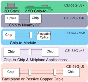
OIF’s CEI specifications are developed for different electrical interconnect reaches and applications to ensure system service and connectivity interoperability at the physical level:

  • USR: Ultra-short reach, for < 10 mm die to optical engine within a multi-chip module (MCM) package.
  • XSR: Extremely short reach, for < 50 mm chip to nearby optical engine (mid-board optics); or CPU to CPU/DSP arrays/memory stack with high-speed SerDes.
  • VSR: Very short reach, < 30 cm chip (e.g. switch chip) to module (edge pluggable cage, such as SFP+, QSFP+, QSFP-DD, OSFP, etc.).

Read full article

Time Sensitive Networking – 3 Benefits it Will Bring to Railway Communication

As demand for mass transit expands in densely populated urban areas, so do passenger demands for more entertainment, on-time delivery and safety. The Industrial Internet of Things (IIoT) and impending technologies like Time-Sensitive Networking (TSN) are making this feasible.

TSN is a novel technology, currently in development at the Institute of Electrical and Electronics Engineers (IEEE), that provides an entirely new level of determinism in standard IEEE 802.1 and IEEE 802.3 Ethernet networks. Standardizing Ethernet networks with TSN will deliver an important capability: deterministic, time-critical packet delivery.

It represents the next measure in the evolution of dependable and standardized automation technology and is certainly the next step in improving railway communication.

Time-Sensitive Networking Will Be Key for Railway Communication

Communication-based train control (CBTC), which uses wireless technologies to continually monitor and control the position of trains, could use TSN to guarantee real-time delivery of critical safety data on Ethernet networks also carrying non-safety related data. Ethernet networks standardized with TSN will support higher data bandwidths and reduce the number of devices required for railway communication. Ultimately, with more information being transmitted across railway Ethernet networks, TSN will ensure that the most critical data is prioritized to assure operations.

What does railway communication look like today, without TSN? The process is like a police car and a truck sharing a one-lane road: Imagine that a truck, (which represents non-time-critical information), is driving along a one-lane road and can’t see anybody behind or in front of him on the road. So, he drives the truck onto the next section of the road. But just as the truck enters this section, a police car (representing time-critical information) with emergency lights arrives and wants to overtake the truck to quickly reach an emergency situation further down the road. unfortunately, the truck has already turned onto the next section of the one-lane road and cannot move out of the way, causing an unexpected delay to the police car!

Read full article

How Cabling Parameters Impact DSP

When dealing with subpar cable and patch cords, it can be frustrating to locate what can cause dropped links – and ultimately downtime and business interruption. When cables aren’t constructed appropriately, performance can be impacted by movement, such as being knocked or bumped, or even frequent moves, adds and changes.

In these situations, return loss of the patch cord can be changed to a point to invalidate the digital signal processing (DSP), or echo cancellation, and cause the link to go down until a new set of parameters is calculated.

As the demands for signal transmission continue to increase, and the tolerance for downtime continues to diminish, the issue of maintaining characteristic impedance for cable becomes even more important.

Keep the Eye Clean

Designers of digital systems often look at the digital signal on an oscilloscope to view its eye pattern. An eye pattern is obtained by superimposing actual waveforms for large numbers of transmitted or received symbols. Eye patterns are used to estimate the bit error rate and the signal-to-noise ratio.

Read full article

Fiber Infrastructure Deployment: Validate Link Budget

Prior to deploying a new fiber cabling infrastructure, or reusing the installed infrastructure, it’s vital to understand the link budget of the selected speed and transceivers in the new architecture, as well as the desired number of connections in each link.

In new fiber infrastructure deployment, more stringent link budget specifications will need higher-quality passive optical components with reduced channel insertion loss in the link. Typically, the low-loss connector not only allows more connections, but also supports longer links with solid performance.

As you get ready for new fiber infrastructure deployment, there are four essential checkpoints that you should keep in mind:

  1. Determine the active equipment I/O interface based on application types
  2. Choose optical link media based on reach and speed
  3. Verify optical fiber standards developed by standards bodies
  4. Validate optical link budget based on link distance and number of connection points

In a series of blogs, we have discussed these checkpoints. This blog covers the final checkpoint (No. 4): validating the optical link budget based on link distances and number of connection points.


Validating the Multimode Link Budget

The current available ultra-low-loss adaptor is 0.2 dB for MPO-8/12 and 0.35 dB for MPO-24 per connection. These enhancements have been achieved by a combination of new material and polishing methods.

read full article

Budgeting Sufficient Power: Key to Future-proof Fiber Infrastructure

With the technology transformations happening in today’s enterprises, many types of organizations – from hotels and gaming facilities to schools and offices – are deploying new fiber cabling infrastructure.

However, it’s crucial to understand the power budget of the new architecture, as well as the desired number of connections in each link. The power budget indicates the amount of loss that a link (from the transmitter to the receiver) can tolerate while maintaining an acceptable level of operation.

This blog provides you with multimode fiber (MMF) link specifications so you can ensure your fiber connections have sufficient power for best performance. In an upcoming blog, we’ll cover the link specifications for singlemode fiber.


 Attenuation and Effective Modal Bandwidth

The latest IEC and ANSI/TIA standards ratified the maximum cabled fiber attenuation coefficients for OM3 and OM4 to 3.0 dB/km for cabled fiber at 850 nm. Attenuation is also known as “transmission loss,” and is the loss of optical power due to absorption, scattering, bending, etc. as light travels through the fiber. OM4 can support a longer reach than OM3, mainly due to its better light-confining characteristics, defined by its effective modal bandwidth (EMB).

Read full article

Checkpoint 3: Optical Fiber Standards for Fiber Infrastructure Deployment

To reinforce the expanding cloud ecosystem, optical active component vendors have designed and commercialized new transceiver types under multi-source agreements (MSAs) for dissimilar data center types; standards bodies are incorporating these new variants into new standards development.

For example, IEEE 802.3 taskforces are working on 50 Gbps- and 100 Gbps-per-lane technologies for next-generation Ethernet speeds from 50 Gbps to 400 Gbps. Moving from 10 Gbps to 25 Gbps, and then to 50 Gbps and 100 Gbps per lane, creates new challenges in semiconductor integrated circuit design and manufacturing processes, as well as in high-speed data transmission.

Getting ready for new fiber infrastructure deployment to accommodate these upcoming changes, there are four essential checkpoints that we think you should keep in mind:

  1. Determine the active equipment I/O interface based on application types
  2. Choose optical link media based on reach and speed
  3. Verify optical fiber standards developed by standards bodies
  4. Validate optical link budget based on link distance and number of connection points

The first blog published on March 23, 2017 – we are discussing these checkpoints, describing current technology trends and explaining the latest industry standards for data center applications. This blog covers checkpoint No. 3: verifying optical fiber standards developed by standards bodies.

Read full article

IT as a Utility

There are accepted utility services which businesses require in order to function: water, gas, sewer and electricity services are at the very top. As public utilities, these services are provided to all organizations; their cost is typically determined based on usage and demand, and customers pay a metered fee based on individual consumption levels.

When you reflect on public utilities, what comes to mind? How reliant we are on them? How fundamental they are to our survival? How the services are primarily invisible to us, and how we often take them for granted?

When you think about it, many of these statements could also be said about IT networks, especially as they have changed over the past few years to support digital buildings and IoT. It’s becoming extremely common to refer to – or think about – IT as a utility because of how central it is to every business – and to our everyday lives. Enterprise networks are just as vital as electricity and water to keeping a business afloat.

Today’s users expect networks to be fast and fully functional. They do not think about the behind-the-scenes work it takes to make that network connection transpire. When you flip a light switch, do you think about where the electricity is coming from, or the process required to make your overhead lights turn on? When you think about IT as a utility, you expect to be able to connect to a network whenever you want – you assume it will always be available and easy to access, regardless of where you are.

Read full article


Category Cables; Planning for Power Delivery

The utilisation of category cables for power delivery has been getting ample attention lately – especially given the amendment in NEC (2017), NFPA 70 (2017) and potentially CEC C22.1 (2017 proposed revisions). This attention is related to potential safety issues that may emerge when high power, high temperature and high cabling density are present.

The National Fire Protection Association (NFPA), Chapter 3, Table 725.144, “Transmission of Power and Data,” contains information about the ampacity rating of conductors at various temperature ratings based on gauge and bundle size. UL has created LP certifications (optional – not required by code) to identify cables that are designed and tested to carry the marked current under reasonable worst-case installation scenarios without exceeding the cable’s temperature rating.

This arose through an allowance in the older version of NEC, which allowed electricians to substitute Class 2 and Class 3 data cables (category cables) for 18 AWG wire in certain instances.

Read full article

Copyright © 2023 Jaycor International
Engineered by: NJIN Agency