Map, Track and Create Connections in Granular Detail with PatchPro®

DCIM – Data Center Infrastructure Management

A Great Solution with a Strong IT Focus Versus Traditional DCIM

Patchpro® I – Infrastructure Connection Manager

Administer your facilities assets and power usage effectiveness, coupled with unprecedented visualization and access to your network architecture, connectivity, and components:

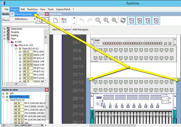
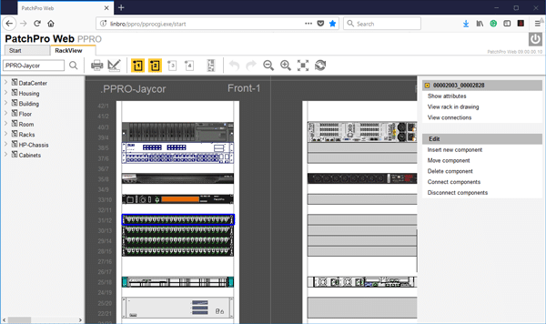
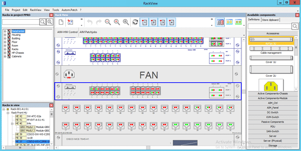
  • Visualize and access racks, inventory and free rack units
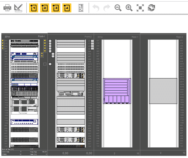
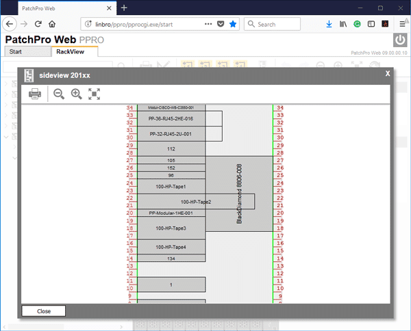
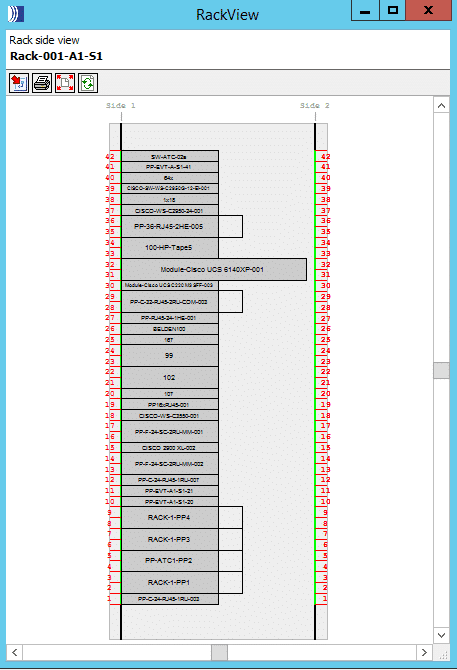
    • Front and rear, back and rear and side views

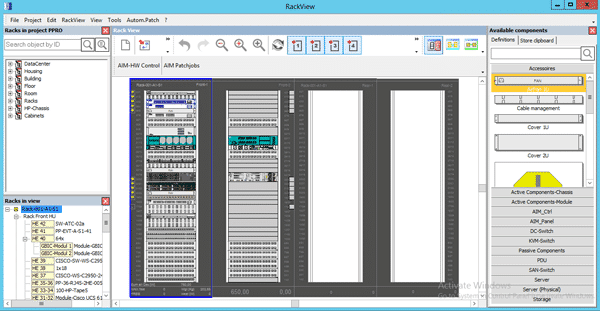
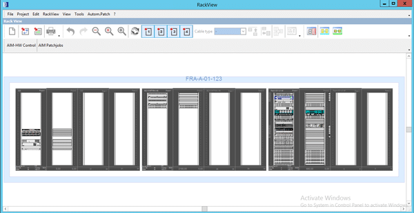
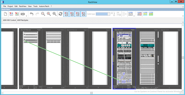
  • Visualize and work on multiple rows, racks, and pods

A Great Solution with a Strong IT Focus Versus Traditional DCIM

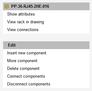
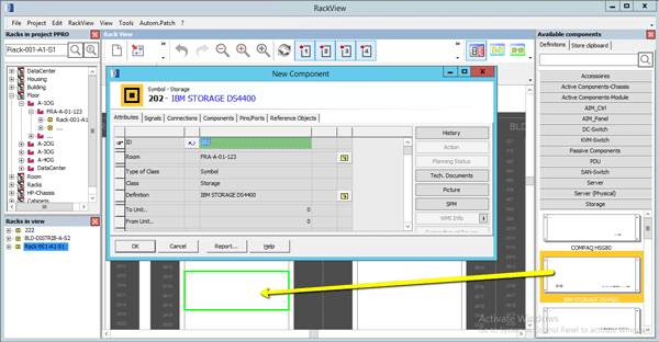
  • Add/subtract components – drag and drop servers, switches, PDU’s, SFP’s Patch panels and more from your component library
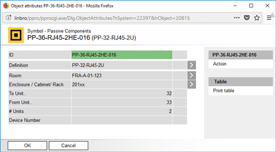
  • New components are saved to the database in real-time with the objects unique set of attributes

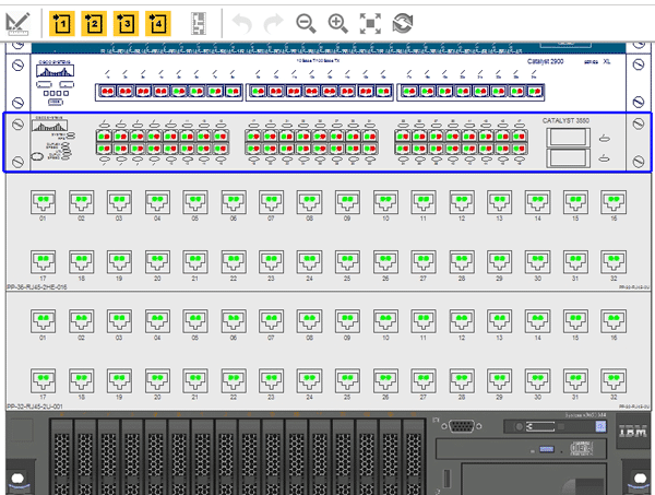
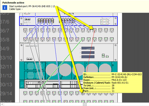
  • Visualize and connect/disconnect free and used ports on devices and patch panels
  • Green – free port
  • Red – connected port

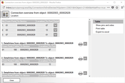
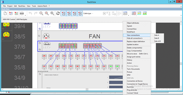
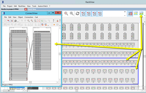
  • Visualize Connections (GUI visually maps connections)
    • Patches between devices within the rack
    • Cross-connects between devices and cabinets
    • Front and Rear Connections
      • ‘View Connections’ quickly visually maps connections
        (Side A, B or A/B)

  • Mouse-hover over free ports to view its connection and the patch objects unique attributes

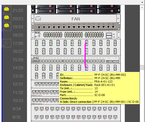
  • Select multiple objects and click ConnectView to map the selections connections
  • Easily export to Microsoft Visio or Excel

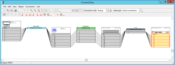
  • End-to-end connectivity literally ‘down to the wire’
    • ConnectView maps any object’s (PC, Server, Switch, cable, port etc.) path from start-to-finish in unprecedented detail

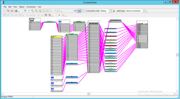
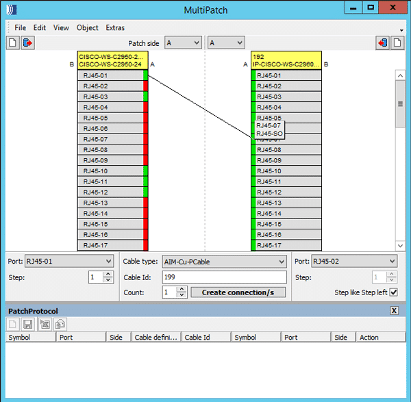
  • Create and visualize patches and cross-connects by clicking on and connecting free ports

  • MultiPatch allows users to create multiple patches between objects, manually or through a .csv (bulk) upload

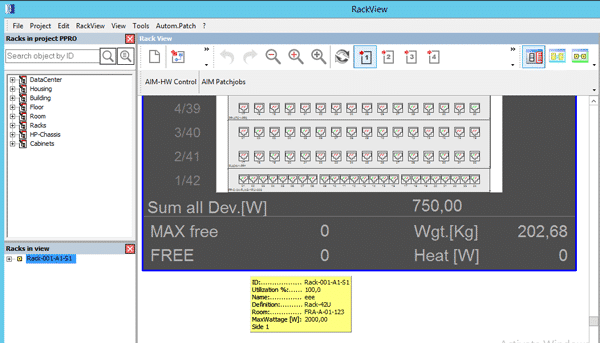
  • Individual racks indicate
  • Total:
    • Energy consumption (W)
    • PDU’s connect via SNMP
    • Weight
    • Free rack units

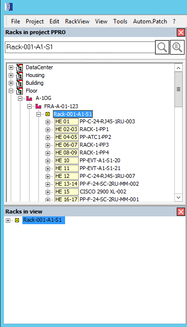
RackView Object Search

  • Search all rack assets using any criteria within the entire facility
    • View the full tree of connectivity from the building down to the device
    • Quickly navigate to the object in RackView by right click or drag & drop into the window
  • RackView – planning mode
    • Design and build your DC and assign work orders to technicians, execute changes once confirmed

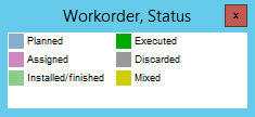
  • Colour indicators on the sides of objects within the rack indicate planned work and the present status
 

1080p Full HD 802.11n Wireless Interactive Presentation Gateway

PLANET WIPG-300H adopting IEEE 802.11n dual-band wireless technology brings smooth display through the 300Mbps high-speed wireless connection or the wired 100Mbps Fast Ethernet connection to project the screen of desktop PC, Mac or smartphone to make the professional and interactive presentation.

Intelligent 1080p Full HD Wireless Projection

The WIPG-300H can optimize resolution based on the automatically transmitting device. It supports the display with multiple resolutions and audio projection disregarding video format and resolution. Its HDMI output resolution can be increased to 1080p (1920 x 1080 pixels), making it a high-definition display perfect for presentation and video. Thus, the office presenter or the home users can easily share the multimedia on the big monitor/screen with others without the hassle of cabling.

Key Features:

  •     Wirelessly project multimedia across different platforms
  •     Flexible dual-output options with VGA or 1080p Full HD resolution
  •     4-to-1 split screen projection increase efficiency
  •     Audio and video streaming
  •     Just Plug & Display by a USB token without any installation
  •     802.11n dual-band Wi-Fi AP and AP-client mode
  •     Remote control presenter’s desktop over USB mouse/keyboard
  •     USB over IP for touch screen and IWB
  •     Web-based management interface
  •     Windows 7/8/10, Mac OS X, iOS and Android support
  •     WebSlides allows multiple users to view the presentation on any mobile devices
  •     SidePad receiver allows a mobile device to remotely control presenter’s desktop
  •     Its compact size makes installation and placement convenient

Wireless Interactive Touch

Furthermore, the WIPG-300H adopts an interactive feature with IWB (Intelligent White Board) and Mobile apps which enable users to reverse control or synchronize screen display for different platforms. This helps the WIPG-300H achieve a real, full wireless presentation environment.

Mobile Applications

The WIPG-300H supports not only the Windows and Mac platforms, but also the presentation and screen mirroring through the iPad, iPhone, or the Android mobile device. Apps for mobile devices working on the WIPG-300H are freely available at Google Play and Apple App Store.

Flexible Projection via Dual Video Output Interfaces

To deliver a perfect presentation solution, the WIPG-300H offers the choice of the two types of video output interfaces: the VGA or HDMI connector, which is compatible with most of the popular display devices. With the hardware decoding capability, the WIPG-300H can project high-definition sound film through wireless or wired LAN connections. It facilitates multiple users to freely display the presentations, images and videos via connecting to a projector or LCD TV without complex installation.

Remote Desktop

Plug standard USB keyboard or mouse into the USB port on the front panel of the WIPG-300H to enable you to control your PC remotely. You don’t have to stand still beside the PC or the WIPG-300H, thus delivering your presentation easily and freely.

4-to-1 Split Screen Projection

With this 4-to-1 split screen feature, the WIPG-300H allows up to four PC / Laptop screens to be projected through one projector at the same time. Therefore, the participants can easily do the side-by-side comparison from four PCs/laptops to make the presentation more efficient.

Empower your Data Centre Collocation Customers with PatchPro® Web

Real-time Online Access to Hosted Infrastructure

PatchPro® Web application provides a collocation data centre’s clients access to their hosted infrastructure, online through a user-friendly web interface. An amazing tool for empowering DC customers to access and view their network infrastructure, servers and other devices. View free ports and rack units, create patch or cross-connects between devices and send workorders direct to the NOC.

The results:

  • Provide Visibility
  • Improve Efficiency
  • Empower Customers

Web Features

Front (and back) and rear (and back) views provide full visibility of all hosted infrastructure within the rack.

– user level access restricts collocations customers from accessing and viewing other customers infrastructure.

Side rack view provides visibility in ensuring no conflicting space requirements apply, when adding additional hardware components.

Visualize connections in granular detail:

– Connected/open ports (front and back) visually

– All connected devices

– Export to Excel/Visio

Customers manage their infrastructure and connectivity

– Components (Servers, switches, SFP’s)

– Create Connections (Patches & Cross-Connects)

Access unique attributes for all connected devices


Additional Benefits of PatchPro® SaaS

  • SaaS (Software as a service)
    • No capital investment in licensing, hardware, staff and training required to execute
    • Contract based on your scope of work and customized for your requirements and budget
  • Open API

Other Modules (Included)

  • PactchPro® F – Facilities Manager
    • Infrastructure physical Layer management (iPLM)
  • PatchPro®I – Infrastructure Connection Manager
    • Data Centre Infrastructure management (DCIM)
    • Automated Infrastructure Management (AIM)
  • PatchPro® SPM Web
    • Service Plan Manager/Asset Managment


Greg Pokroy

CEO – JAYCOR International

Supporting Your Future of Network Technology: 6 Ways to Design Layer 0

The year 2014 was a key moment for the structured cabling industry. That is when the number of devices on the Internet officially surpassed the number of people on the Internet. In other words, we’re carrying and using more connected devices than ever before. Since then, Internet of Things (IoT) has begun to take over conversations about technology. Digital buildings – which feature a connected infrastructure to bring building systems together via the enterprise network – are moving to the forefront.

With these changes, how can you design your cabling infrastructure – your layer 0 – to support network technology changes? Every structured cabling system is unique, designed to fit a company’s specific needs. Taking the future into account during cabling projects helps maximize your investment while decreasing long-term costs. With correct planning and design, you’ll be ready for future hardware and software upgrades, be able to support increasing numbers of devices joining your network and will be set to accommodate higher-speed Ethernet migrations, such as 40G/100G.

We have gathered our best pieces of advice on how to design your layer 0 to support the future of network technology.


1. Abide by Cabling Standards

To provide guidance and best practices for the lifetime of your layer 0, following standards for structured cabling systems allows for the mix of products from different vendors and also helps in future moves, adds and changes:

  • TIA , North American standards for things like telecommunications cabling (copper and fiber), bonding and grounding, and intelligent building cabling systems
  • ISO/IEC, global standard harmonized with TIA networking standards
  • IEEE, which creates Ethernet-based standards for networks and relies on TIA and ISO/IEC layer 0 standards

2. Invest in High-Performance Cables

When your cabling system is designed to be used across multiple generations of hardware, it can remain in place longer while supporting fast and easy hardware upgrades.

Analyze how your business is currently run, as well as any expected business or technology shifts in the years to come. Then match these requirements with the performance characteristics of the cabling systems you’re considering.

Make sure that the category cabling can:

  • Support the full 100m distance per channel
  • Accommodate a tight bend radius inside wall cavities and other tight spaces
  • Support the highest operating temperature rating possible with low DC resistance
  • Maintain excellent transmission performance
  • Be bundled or tightly packed into trays and pathways without performance issues

Most Category 6A cables offer all of the benefits mentioned above, making Category 6A a solid decision that will support the future of network technology.

3. Find a Reputable Warranty

One of the best ways to ensure that your cabling and connectivity solutions will last is to find products that are backed by extensive and impressive warranties (such as a 25-year warranty).

When layer 0 is properly designed and installed, the structured cabling system will support your short-term and long-term needs. A reliable warranty ensures that this happens. For example, with a 25-year warranty, the installed system should meet or exceed industry standards for 25 years, as well as support future standards and protocols. If this isn’t the case, the manufacturer should address the issue.

Read full article

The Evolution of Wireless Standards

In the late 1990’s, one of the first wireless standards was carried out. You may remember IEEE 802.11b – the first wireless LAN standard to be widely adopted and incorporated into computers and laptops. A few years later on came the IEEE 802.11g, which offered signal transmission over relatively short distances at speeds of up to 54 Mbps. Both standards operated in the unlicensed 2.4 GHz frequency range. In 2009, IEEE 802.11n (which operated in 2.4 GHz and 5 GHz frequency ranges) was a big step up. It provided anytime wireless access and was the de facto standard for mobile users.

Understanding wireless technology and standards like these is key to making sure you are investing in technology and equipment that can support your organisation’s short-term and long-term network-connection requirements. Wireless standards layout specific specifications that must be followed when hardware or software are designed related to those standards.

Now that we have covered the major wireless standards of the past, let’s look ahead at current standards – and what is yet to come.


General-Purpose Applications

Today’s wireless standards, like IEEE 802.11ac (Wave 1 and Wave 2), operate in the 5 GHz frequency range. This standard is used for many general-purpose, short-range, multi-user applications, like connecting end devices to networks.

As we have mentioned in previous blogs, IEEE 802.11ax is the “next big thing” in terms of wireless standards. As the successor to 802.11ac, 802.11ax operates in both the 2.4 GHz and 5 GHz frequency spectrums. It will offer 10G speeds, and the ability for multiple people to use one network simultaneously with fewer connectivity problems (and while still maintaining fast connection speeds). It will improve average throughput per user by a factor of at least four as compared to 802.11ac Wave 1.


High-Performance Applications

Operating at an unlicensed frequency of 60 GHz are IEEE 802.11ad and IEEE 802.11ay, which are used primarily for short-range, point-to-point applications vs. point-to-multipoint applications. 802.11ay is an update to 802.11ad, improving throughput and range. As compared to 802.11ad, 802.11ay can offer speeds between 20Gbps and 40Gbps, as well as an improved range.


IoT Applications

Operating at lower frequencies are standards like 802.11af (UHF/VHF) and 802.11ah (915 MHz). These standards are designed for extended-range applications, like connecting hundreds of remote Internet of Things (IoT) sensors and devices. They’re also used in rural areas.

Because they operate in lower-frequency ranges, they’re able to offer extended operational ranges. They can carry signals for miles, but have a low throughput of 350 Mbps.

Read full article

Public vs Private Clouds: How Do You Choose?

An Intel Security survey of 2,000+ IT professionals last year revealed several fascinating information about public and private cloud adoption. For starters, within the next 15 months, 80% of all IT budgets will have some income dedicated to cloud solutions.

Many enterprises are starting to rely on public and private clouds for a few simple reasons:

  • Most good public and private cloud providers regularly and automatically back up data they store so it is recoverable if an incident occurs.
  • Tasks like software upgrades and server equipment maintenance become the responsibility of the cloud provider.
  • Scalability is virtually unlimited; you can grow rapidly to meet business needs, and then scale back just as quickly if that need no longer exists.
  • Upfront costs are lower, since cloud computing eliminates the capital expenses associated with investing in your own space, hardware and software.

But before you decide you are moving to the cloud, you should know the differences between public and private clouds. Making a choice between public and private clouds often depends on the type of data you’re creating, storing and working with.


Public Clouds Defined

The public cloud got its kick start by hosting applications online – today, however, it has evolved to include infrastructure, data storage, etc. Most people do not  realise that they have been benefitting from the public cloud for years (before most of us even referred to “public and private clouds”). For example, any time you access your online banking tool or login to your Gmail account, you’re using the public cloud.

In a public cloud, data center infrastructure and physical resources are shared by many different enterprises, but owned and operated by a third-party services provider (the cloud provider). Your company’s data is hosted on the same hardware as the data from other companies. The services and infrastructure are accessible online. This allows you to quickly scale resources up and down to meet demand. As opposed to a private cloud, public cloud infrastructure costs are based on usage. When dealing with the public cloud, the user/customer typically has no control (and very limited visibility) regarding where and how services are hosted.


Private Clouds Defined

In a private cloud, infrastructure is either hosted at your own onsite data center or in an environment that that can guarantee 100% privacy (through a multi-tenant data center or a private cloud provider). In these third-party environments, the components of a private cloud (computing, storage and networking hardware, for example) are all dedicated solely to your organization so you can customize them for what you need. In some cases, you’ll even have choices about what type of hardware is used. No other organization’s data will be hosted using the equipment you use.

With an internal private cloud (one hosted at your own data center), your enterprise incurs the capital and operating costs associated with establishing and maintaining it. Many of the benefits listed earlier about choosing cloud services don’t apply to internal private clouds, especially since you serve as your own private cloud provider.

In organizations and industries that require strict security and data privacy, private clouds usually fit the bill because applications can be hosted in an environment where resources aren’t shared with others; this allows higher levels of data security and control as compared to the public cloud.


What’s a Hybrid Cloud?

Enterprises also have the opportunity to take advantage of both the public and private cloud by implementing a hybrid cloud, which combines the two.

For example, the public cloud can be used for things like web-based email and calendaring, while the private cloud can be used for sensitive data.

Read full article

The Impact of Patch Cord Types on the Network

Data Centers and the networks they support have expanded to be an integral part of every business. The software applications that keep mission-critical operations up and running in highly redundant, 24/7 environments rely on highly engineered structured cabling systems to connect the cloud to every user. Structured cabling is the foundation that supports data centers.

Although structured cabling is not as sexy as diesel-driven UPS systems or adiabatic cooling systems, it contributes a huge role in supporting the cloud. One important component of structured cabling that is often overlooked: patch cords.

Oftentimes, patch cords are purchased haphazardly and installed at the last minute. But the right patch cord type can improve the performance of your network. The proper design, specification, manufacturing, installation and ongoing maintenance of patch cord systems can help ensure that your network experiences as much uptime as possible.

A patch cord problem can wreak havoc on an enterprise, from preventing an airline customer from making a necessary reservation change to keeping a hotel guest from getting work done while on business travel.

What Drives Data Growth?

Explosive data growth due to social media, video streaming, IoT, big data analytics and changes in the data center environment (virtualization, consolidation and high-performance computing) means one thing: Data traffic is not only growing in bandwidth, but also in speed.

Another essential point is network design. Today’s network design, such as a leaf-spine fabric, makes the network flatter, which lowers latency – this makes the Ethernet and corresponding patch cord types incredibly important.

The Definition of a Patch Cord

A patch cord is a cable with a connector on both ends (the type of connector is a function of use). A fiber patch cord is sometimes referred to as a “jumper.”

Patch cords are part of the local area network (LAN), and are used to connect network switches to servers, storage and monitoring portals (traffic access points). They are considered to be an integral part of the structured cabling system.

Copper patch cords are either made with solid or  stranded copper; due to potential signal loss, lengths are typically shorter than connector cables.

A fiber patch cord is a fiber optic cable that is capped at both ends with connectors. The caps allow the cord to be rapidly connected to an optical switch or other telecommunications/computer device. The fiber cord is also used to connect the optical transmitter, receiver and terminal box.

Read full article

Single-Pair Ethernet Cabling: Four New Applications

Four New Types of Single-Pair Ethernet Cabling

For years, Ethernet cabling has used four twisted pairs to carry data without worrying about noise in data lines. Recent developments in IEEE 802.3 (Ethernet Working Group) and TIA TR-42(Telecommunications Cabling Systems Engineering Committee) has unveiled four standards projects which may change that; instead of four balanced twisted-pairs cabling, these standards feature a single balanced twisted-pair Ethernet cabling.

Of these four, one will impact enterprise networks the most. We will cover this standard first, and then explain the three other types of single-pair Ethernet cables below.

IoT 1 Gbps Applications: 100 m Reach

2017 Ericsson Mobility Report says that there will be nearly 28 billion connected devices in place globally by 2021 – and more than half of these will be related to Internet of Things (IoT).

With the ability to deliver data at speeds of up to 1G, and PoE power, this standard is intended specifically for IoT applications. Known as ANSI/TIA-568.5, it will provide cable, connector, cord, link and channel specifications for single-pair connectivity in enterprise networks.

This single-pair Ethernet cable may help network professionals connect more devices to their networks as the industry moves toward digital buildings – where all types of systems and devices integrate directly with the enterprise network to capture and communicate data.

Most of the devices used in digital buildings – such as sensors – have minimal power and bandwidth requirements (in applications like building automation and alarm systems). In these cases, single-pair Ethernet cable can provide a cost-effective cabling solution. The cable is smaller and lighter than a standard four-pair Ethernet cable, so it can also reduce pathway congestion.

The three other single-pair Ethernet cable types don’t apply directly to data centers or enterprise networks, but they’re still important to understand.

Read full article

Better, Faster, Cheaper Ethernet: The Road From 100G to 800G

Worldwide IP traffic has been increasing immensely in the enterprise and consumer division, driven by growing numbers of Internet users, as well as growing numbers of connected devices that provide faster wireless and fixed broadband access, high-quality video streaming and social networking capabilities.

Data centers are expanding globally to support computing, storage and content delivery services for enterprise and consumer users. With higher operation efficiency (CPU usage), higher scalability, lower costs and lower power consumption per workload, cloud data centers will process 92% of overall data center workloads by 2020; the remaining 8% of the workload will be processed by traditional data centers.

According to the Cisco Global Cloud Index 2015-2020, hyperscale data centers will grow from 259 in 2015 to 485 by 2020, representing 47% of all installed data center servers.

Cisco Global Cloud Index

Source: Cisco

Global annual data center traffic will grow from 6.5 ZB (zettabytes) in 2016 to 15.3 ZB by 2020. The majority of traffic will be generated in cloud data centers; most traffic will occur within the data center.

When it comes to supporting cloud business growth, higher performance and more competitive services for the enterprise (computing and collaboration) and consumers (video streaming and social networking), common cloud data center challenges include:

  • Cost efficiency
  • Port density
  • Power density
  • Product availability
  • Reach limit
  • Resilience (disaster recovery)
  • Sustainability
  • System scalability

This is the first in a series of seven blogs that will appear throughout the rest of 2017; in this series, we’ll walk you down the road to 800G Ethernet. Here, we take a close look at Ethernet generations and when they have (or will) come into play.

Read full article

Fiber Infrastructure Deployment: Validate Link Budget

Prior to deploying a new fiber cabling infrastructure, or reusing the installed infrastructure, it’s vital to understand the link budget of the selected speed and transceivers in the new architecture, as well as the desired number of connections in each link.

In new fiber infrastructure deployment, more stringent link budget specifications will need higher-quality passive optical components with reduced channel insertion loss in the link. Typically, the low-loss connector not only allows more connections, but also supports longer links with solid performance.

As you get ready for new fiber infrastructure deployment, there are four essential checkpoints that you should keep in mind:

  1. Determine the active equipment I/O interface based on application types
  2. Choose optical link media based on reach and speed
  3. Verify optical fiber standards developed by standards bodies
  4. Validate optical link budget based on link distance and number of connection points

In a series of blogs, we have discussed these checkpoints. This blog covers the final checkpoint (No. 4): validating the optical link budget based on link distances and number of connection points.


Validating the Multimode Link Budget

The current available ultra-low-loss adaptor is 0.2 dB for MPO-8/12 and 0.35 dB for MPO-24 per connection. These enhancements have been achieved by a combination of new material and polishing methods.

read full article

Copyright © 2023 Jaycor International
Engineered by: NJIN Agency