Map, Track and Create Connections in Granular Detail with PatchPro®

DCIM – Data Center Infrastructure Management

A Great Solution with a Strong IT Focus Versus Traditional DCIM

Patchpro® I – Infrastructure Connection Manager

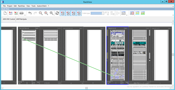
Administer your facilities assets and power usage effectiveness, coupled with unprecedented visualization and access to your network architecture, connectivity, and components:

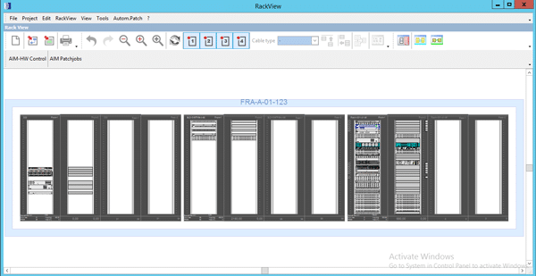
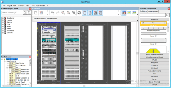
  • Visualize and access racks, inventory and free rack units
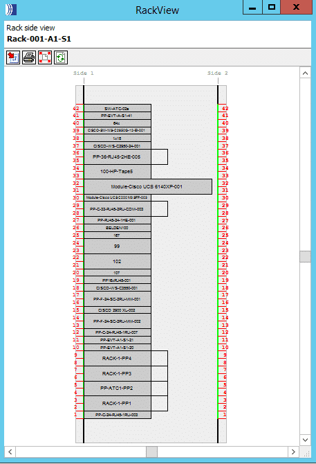
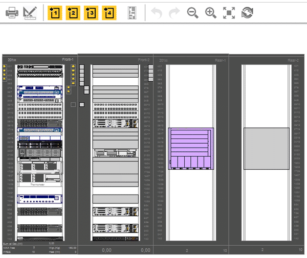
    • Front and rear, back and rear and side views

  • Visualize and work on multiple rows, racks, and pods

A Great Solution with a Strong IT Focus Versus Traditional DCIM

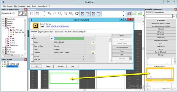
  • Add/subtract components – drag and drop servers, switches, PDU’s, SFP’s Patch panels and more from your component library
  • New components are saved to the database in real-time with the objects unique set of attributes

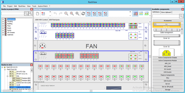
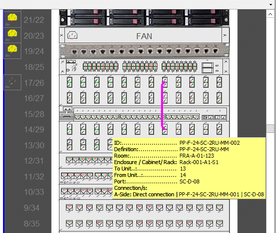
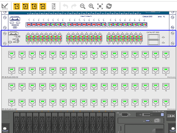
  • Visualize and connect/disconnect free and used ports on devices and patch panels
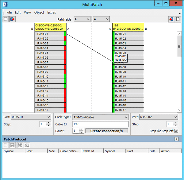
  • Green – free port
  • Red – connected port

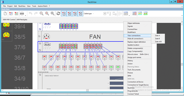
  • Visualize Connections (GUI visually maps connections)
    • Patches between devices within the rack
    • Cross-connects between devices and cabinets
    • Front and Rear Connections
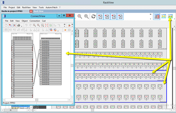
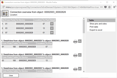
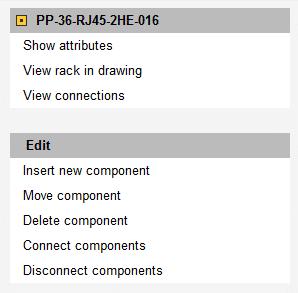
      • ‘View Connections’ quickly visually maps connections
        (Side A, B or A/B)

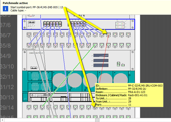
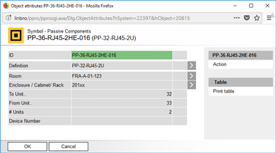
  • Mouse-hover over free ports to view its connection and the patch objects unique attributes

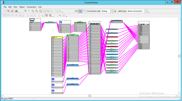
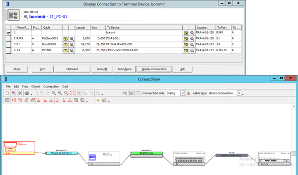
  • Select multiple objects and click ConnectView to map the selections connections
  • Easily export to Microsoft Visio or Excel

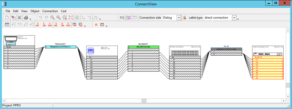
  • End-to-end connectivity literally ‘down to the wire’
    • ConnectView maps any object’s (PC, Server, Switch, cable, port etc.) path from start-to-finish in unprecedented detail

  • Create and visualize patches and cross-connects by clicking on and connecting free ports

  • MultiPatch allows users to create multiple patches between objects, manually or through a .csv (bulk) upload

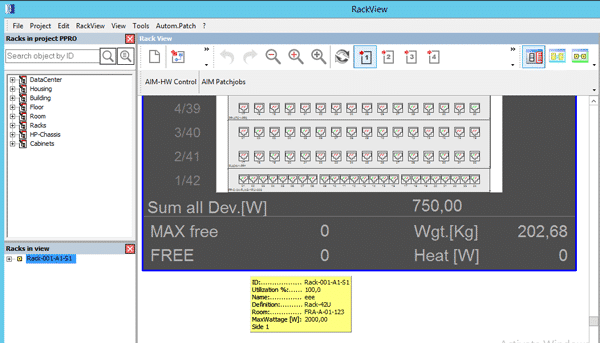
  • Individual racks indicate
  • Total:
    • Energy consumption (W)
    • PDU’s connect via SNMP
    • Weight
    • Free rack units

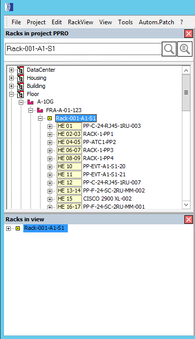
RackView Object Search

  • Search all rack assets using any criteria within the entire facility
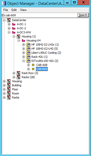
    • View the full tree of connectivity from the building down to the device
    • Quickly navigate to the object in RackView by right click or drag & drop into the window
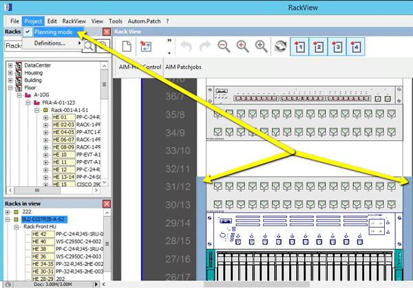
  • RackView – planning mode
    • Design and build your DC and assign work orders to technicians, execute changes once confirmed

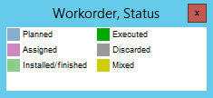
  • Colour indicators on the sides of objects within the rack indicate planned work and the present status
 

A Genius Tool for Effective Facilities Management – PatchPro®

PatchPro® F – iPLM Infrastructure Physical Layer Management
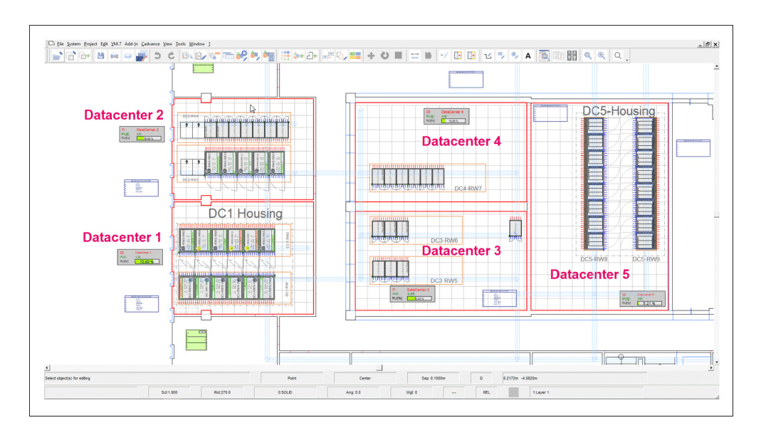
Design, Build & Manage your Enterprise and Data Centre in Granular Detail

iPLM View

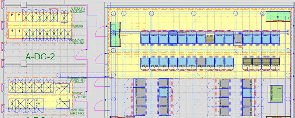
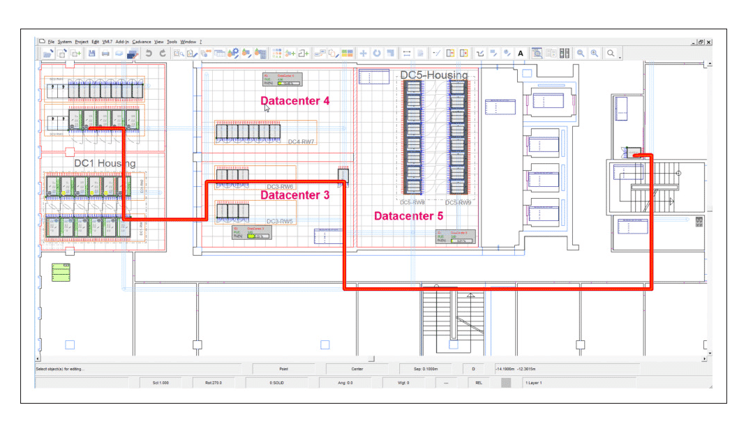
The iPLM View enables the user to access and visualize all objects, their attributes and cost centre’s within the entire facility:

  • All infrastructure (shown per floor)
    • Power distribution
      • DB Boards
      • Cabling, routes, and ducts
    • Ventilation ducts and CRAC Units
    • Cost Centre and PUE (real-time)
    • All other assets – offices/free space, PC’s, furniture

  • All network infrastructure and connectivity
    • Cabling, patch cords, wall-jacks, cable routes, and ducts
    • All connections from start-device through the network (point-to-point) to end-device

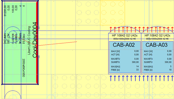
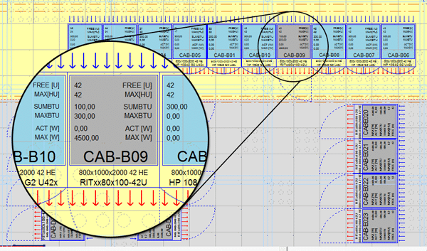
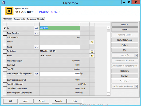
  • Cabinet/rack – real-time visualization of:
    • Dimensions (e.g. 800x1000x2000 42RU)
    • Free Rack Units
    • Sum of and Max BTU’s
    • Actual and Max Wattage
    • customize

  • Search (keywords) the object manager in granular detail for any criteria/objects within the entire facility
  • Quickly and easily navigate/zoom to the asset, view its connections and attributes

  • DC Managers create real-time design changes in planning mode and deploy work orders for execution.

IoT is Here to Stay: The Evolution of Converged Networks

Lately, I’ve been reminded of a quote that’s often attributed to Charles Darwin: “… It is not the most intellectual of the species that survives; it is not the strongest that survives, but the species that survives is the one that is able best to adapt and adjust to the changing environment in which it finds itself.”

The idea behind this quote remains true and applies well beyond the field of evolutionary biology.

Convergence (version 2.0) is here, and, to survive, we need to adjust, change and adapt to our changing environment. We cannot build networks for today (and for the future) like we have built them in the past, lest we go the way of the dodo bird.

Let’s look at the changes and improvements made since the first converged network (Convergence 1.0).

the-evolution-of-converged-networks-iot-is-here-to-stay-image-1

We established networks in the voice world that operated on high-availability systems we could count on without question. When you picked up the handset, you had a dial tone. With the rapid growth of data networks starting in the ’70s, it was inevitable that the industry would find synergies to allow voice and data telecommunications to exist on the same converged network.

the-evolution-of-converged-networks-iot-is-here-to-stay-image-2

In hindsight, I would argue that the technological and engineering issues were actually the easiest to overcome. The most difficult were the people issues: resistance to or fear of change, ego, protectionism, organizational boundaries, and risk avoidance, to name just a few. As the technologies grew, evolved and improved, so did our understanding. This helped us break down and overcome the people issues. A converged network bringing voice and data together is now the norm.

I’ve had a number of recent discussions with user groups in regard to the Internet of Things (IoT) and the opportunity that new technologies, applications and devices bring to an organization, as well as the challenges that can arise in adapting to this changing environment.

Traditionally, machine-to-machine (M2M) or device-based networks sat outside our converged networks, whether they be for digital building technologies, like video and security; smart cars; industrial networks; or many others.

the-evolution-of-converged-networks-iot-is-here-to-stay-image-3

In an IoT world, those networks still exist, as they always have. They may work on the same physical and/or logical networks with the same cables, boxes, and software, or they may use “like” networks to better interact.

The IoT world is here, and the level and rate of convergence are increasing in volume and velocity. IoT is a nebulous concept – hence all the cloud analogies. It will continue to morph as technologies evolve along with those that use it. Your corporate IoT cloud will look different from mine, and that’s okay.

the-evolution-of-converged-networks-iot-is-here-to-stay-image-4

Will we ever get to a true hyper-converged network where anything can talk to anything at any time? I don’t know – but that’s a people issue, not an engineering one. My lack of understanding or foresight doesn’t mean I don’t need to adjust and prepare for that eventuality. Converged networks will grow as they have; I will grow and adapt, or else I risk the potential of not being able to function in my changing environment.

Which brings me to adapting and adjusting to a changing environment from a network infrastructure frame of mind. Our TIA TR-42 (Telecommunications Cabling Systems ANSI/TIA-568 family), BICSI (TDMM and others) and proprietary or third documents must adapt and adjust. Whether they be specifications, standards or best-practice resources, they must evolve or face irrelevance (extinction, to extend the metaphor).

Our converged networks have evolved with higher speeds, higher power and more portability or mobility than ever before. More than any pundit, I remember prognosticating in the ’90s when people were amazed at shared megabit network capabilities and the ability to talk on the phone untethered. Simply creating faster networks, with higher grades of cabling, is not the answer.

Improvements in speed, noise immunity, power, portability, and mobility are all important, but they alone won’t get us where we need to go. We need to think differently, challenge the status quo and create new solutions. We need to adjust and adapt.

Traditional network guidance has usually centered on human telecommunications, whether directly, through things like voice and video, or indirectly through human-controlled devices, like our computers and tablets. Devices have been communicating through artificial means at least as long as we have, either through mechanical wires, pneumatics, hydraulics, electronic signals or other means. But now those machines are joining us in the digital world; rather than relying on proprietary protocols, they can now run on the same networks that our human-controlled devices do.

The bias toward human-controlled telecommunications is natural given the nature of standards development. Almost every standard defines “user” as a primary consideration when designing networks. Devices, despite having the ability to communicate on the same networks, have noticeably different requirements and, therefore, need different considerations. A one-size-fits-all approach to network design has arguably never worked well; it certainly won’t for our digital buildings and IoT environment of the future.

Using the smart building example, a “user” is a transient device on the network. The user goes home at the end of the day and on holidays, and user groups or customers change over with leases and occupancy changes. The lights, door controls, surveillance, security, mechanical and other digital building systems are effectively permanent fixtures. Our laptops, phones, and tablets are typically refreshed every few years. A building’s systems and technologies are expected to last much longer than that.

Furthermore, the operational risks, concerns, needs, and security requirements are different from “users” to “devices.” A person can get sick or take a vacation; a building cannot. The lights must always turn on, the HVAC systems must always work, the doors must always open, close and secure – without question. Even though a door control, lighting or HVAC system may not require the same bandwidth as a user, it does not mean that their network has lesser requirements. If anything, they may have higher requirements in some areas. If my laptop doesn’t function, I can still connect with my tablet or my phone. If a building doesn’t function, it impacts all the users – not just one.

I know that industry standards and best practices are adapting and adjusting to a new environment. Make sure your practices, specifications, assumptions, and procedures do as well. Otherwise, we risk new technology becoming an impediment to our goals – not through any fault of its own, but rather through how it was implemented. Make sure your team members, both external and internal, remember the lessons of Convergence 1.0 so they can be ready for 2.0, which is happening now. “We’ve always done it this way” might as well have been the mantra of the dodo bird.
Full article

1080p Full HD 802.11n Wireless Interactive Presentation Gateway

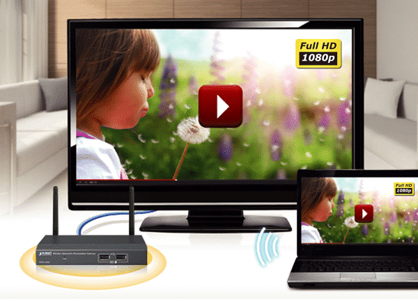
PLANET WIPG-300H adopting IEEE 802.11n dual-band wireless technology brings smooth display through the 300Mbps high-speed wireless connection or the wired 100Mbps Fast Ethernet connection to project the screen of desktop PC, Mac or smartphone to make the professional and interactive presentation.

Intelligent 1080p Full HD Wireless Projection

The WIPG-300H can optimize resolution based on the automatically transmitting device. It supports the display with multiple resolutions and audio projection disregarding video format and resolution. Its HDMI output resolution can be increased to 1080p (1920 x 1080 pixels), making it a high-definition display perfect for presentation and video. Thus, the office presenter or the home users can easily share the multimedia on the big monitor/screen with others without the hassle of cabling.

Key Features:

  •     Wirelessly project multimedia across different platforms
  •     Flexible dual-output options with VGA or 1080p Full HD resolution
  •     4-to-1 split screen projection increase efficiency
  •     Audio and video streaming
  •     Just Plug & Display by a USB token without any installation
  •     802.11n dual-band Wi-Fi AP and AP-client mode
  •     Remote control presenter’s desktop over USB mouse/keyboard
  •     USB over IP for touch screen and IWB
  •     Web-based management interface
  •     Windows 7/8/10, Mac OS X, iOS and Android support
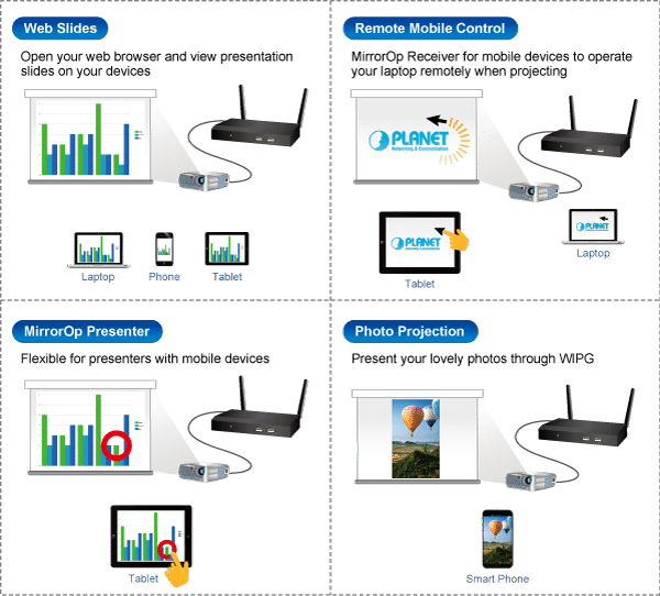
  •     WebSlides allows multiple users to view the presentation on any mobile devices
  •     SidePad receiver allows a mobile device to remotely control presenter’s desktop
  •     Its compact size makes installation and placement convenient

Wireless Interactive Touch

Furthermore, the WIPG-300H adopts an interactive feature with IWB (Intelligent White Board) and Mobile apps which enable users to reverse control or synchronize screen display for different platforms. This helps the WIPG-300H achieve a real, full wireless presentation environment.

Mobile Applications

The WIPG-300H supports not only the Windows and Mac platforms, but also the presentation and screen mirroring through the iPad, iPhone, or the Android mobile device. Apps for mobile devices working on the WIPG-300H are freely available at Google Play and Apple App Store.

Flexible Projection via Dual Video Output Interfaces

To deliver a perfect presentation solution, the WIPG-300H offers the choice of the two types of video output interfaces: the VGA or HDMI connector, which is compatible with most of the popular display devices. With the hardware decoding capability, the WIPG-300H can project high-definition sound film through wireless or wired LAN connections. It facilitates multiple users to freely display the presentations, images and videos via connecting to a projector or LCD TV without complex installation.

Remote Desktop

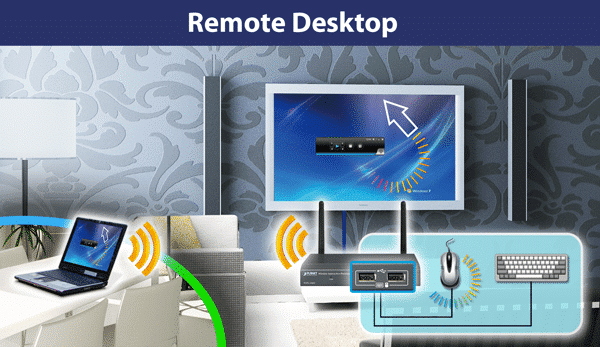
Plug standard USB keyboard or mouse into the USB port on the front panel of the WIPG-300H to enable you to control your PC remotely. You don’t have to stand still beside the PC or the WIPG-300H, thus delivering your presentation easily and freely.

4-to-1 Split Screen Projection

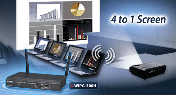
With this 4-to-1 split screen feature, the WIPG-300H allows up to four PC / Laptop screens to be projected through one projector at the same time. Therefore, the participants can easily do the side-by-side comparison from four PCs/laptops to make the presentation more efficient.

Cost Effective Industrial Wifi

Now available in stock – JAYCOR offers a complete end-to-end solution for cost-effective industrial/outdoor ruggedized Wifi. Purchase all components for a turnkey solution:

  • Wireless AP (Access Point)
  • Omni or directional antennas
  • Antenna (N-Type) & Ethernet (RJ45) patch cords
  • Antenna & Ethernet lighting surge protection
  • Din Rail /Wall Mount PoE Switches, Media Converters and SFP modules
  • Din Rail Power Supplies & cabtyre
  • Outdoor enclosure


Common Questions: HDBaseT

HDBaseT has become the leading solution for delivering ultra-high-definition (UHD) 4K video and audio, USB 2.0, 100 MB Ethernet, control and 100W on a single cable. This is what the HDBaseT Alliance refers to as the “5Play™ feature set.” It’s a huge benefit to have one cable that supports all these applications up to 330 ft for AV installations.

How HDBaseT Works with HDMI

The HDMI connector has become the industry standard for AV applications. It’s estimated that there are more than 4 billion HDMI devices currently in use. The HDMI 1.4 specification requires bandwidth of almost 10 Gbps. The HDMI 2.0 specification requires 18 Gbps, and the new HDMI 2.1 specification requires 48 Gbps. It’s clear that we’re seeing a rapid increase in bandwidth demand.
HDMI cables, however, have some distance limitations. Anything longer than 15 ft should have a chip to boost the signal (directional). Anything longer than 50 ft should be over active optical connection (AOC). Note: Cable distances supported for the newest 2.1 specification are still unclear because products are not available yet. In addition to distance limitations, HDMI can be difficult to install because the cables aren’t typically field terminated. These limitations cause real problems, especially in commercial installations.
This is where HDBaseT steps in. It can take the HDMI input, along with the other 5Play technology signals, and transport it 330 ft over a field-terminable, 4-pair twisted copper cable. Not only can you achieve longer distances, but, with the use of a switch, you can use multiple inputs and outputs.

Although HDBaseT was originally intended to work with standard category cabling, there have been some issues. As a result, we recommend that you choose a cable designed for the HDBaseT system you’re implementing.

The Best Cabling System for HDBaseT

Belden has performed several cabling tests to analyze bundling, power and 4K performance among different cabling systems. These tests have identified the cabling that can reliably support HDBaseT technology.

During testing, key parameters were identified in HDBaseT signal and design. This resulted in Belden’s creation of the industry’s first cable designed specifically for HDBaseT 4K video. These key electrical parameters are increased over standard category cable while still maintaining a cable that’s easy to install due to size and flexibility.

Read full article

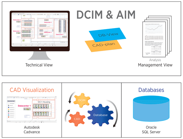
How PatchPro® Works

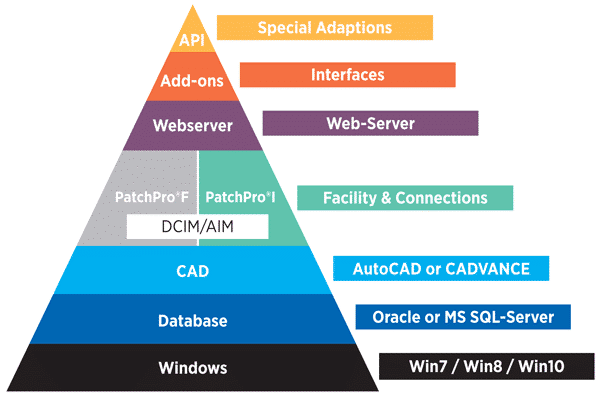
The key point is the Database

  • The Database sends all information / changes to the raphical user interface (GUI) through CADVANCE and or AutoCAD
  • The advantage of PatchPro is that you can manipulate the database by using the GUI which is quicker and easier
  • The Database and the GUI are connected. Objects changed on the system update in real-time

Key attributes of PatchPro® Software Solutions

Comprehensive technical functionality – both in the Facilities as well as in Data Centres.

  • Graphical User Interface’s (GUI) display:
  • Entire Facility & Multiple Site
  • Data Centre/s
  • Rack View/s
  • Open System (API) and database architecture

Empower your Data Centre Collocation Customers with PatchPro® Web

Real-time Online Access to Hosted Infrastructure

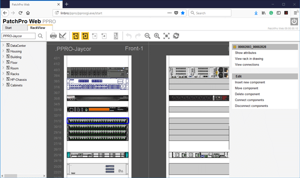
PatchPro® Web application provides a collocation data centre’s clients access to their hosted infrastructure, online through a user-friendly web interface. An amazing tool for empowering DC customers to access and view their network infrastructure, servers and other devices. View free ports and rack units, create patch or cross-connects between devices and send workorders direct to the NOC.

The results:

  • Provide Visibility
  • Improve Efficiency
  • Empower Customers

Web Features

Front (and back) and rear (and back) views provide full visibility of all hosted infrastructure within the rack.

– user level access restricts collocations customers from accessing and viewing other customers infrastructure.

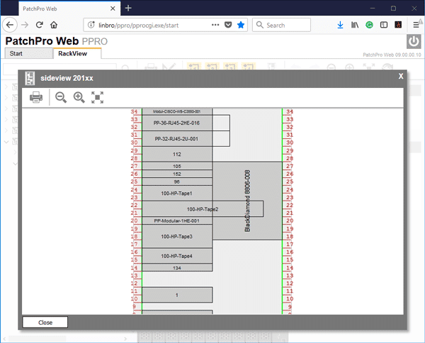
Side rack view provides visibility in ensuring no conflicting space requirements apply, when adding additional hardware components.

Visualize connections in granular detail:

– Connected/open ports (front and back) visually

– All connected devices

– Export to Excel/Visio

Customers manage their infrastructure and connectivity

– Components (Servers, switches, SFP’s)

– Create Connections (Patches & Cross-Connects)

Access unique attributes for all connected devices


Additional Benefits of PatchPro® SaaS

  • SaaS (Software as a service)
    • No capital investment in licensing, hardware, staff and training required to execute
    • Contract based on your scope of work and customized for your requirements and budget
  • Open API

Other Modules (Included)

  • PactchPro® F – Facilities Manager
    • Infrastructure physical Layer management (iPLM)
  • PatchPro®I – Infrastructure Connection Manager
    • Data Centre Infrastructure management (DCIM)
    • Automated Infrastructure Management (AIM)
  • PatchPro® SPM Web
    • Service Plan Manager/Asset Managment


Greg Pokroy

CEO – JAYCOR International

Enhance Performance, Productivity and Well-being with Human-Centric PoE LED Lighting

Power over Ethernet (PoE) makes it easier and more cost efficient to power all the “things” that make up Internet of Things and smart buildings. Why? Because, with PoE, powering these devices doesn’t require a power connection and a data connection. Through a single category cable, both power and data can be delivered to a device.

Prior to PoE, these systems may have been able to come together over one IP network for improved control and monitoring, but they still required separate data and electrical connections, as well as proximity to electrical outlets.

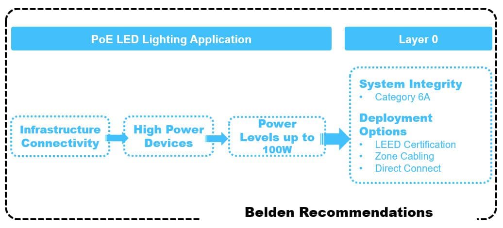
Over the past few years, PoE power levels have been increasing – starting at 15W and growing to 30W and 60W. Today, itp’s possible to deliver 100W of power plus data over a single cable. PoE standards are also changing to support higher power levels. IEEE 802.3bt, which is currently under development, calls for 4-pair power delivery to improve efficiency and support complex devices. It also calls for two power variants: Type 3 (60W) and Type 4 (100W).

These higher wattages allow devices like point-of-sale registers, digital signage displays and PTZ surveillance cameras to take advantage of PoE. LED lighting systems can also now connect to the network via a PoE cable.

Connecting LED lighting systems to the network via PoE offers many benefits. Each fixture can utilize a standard RJ45 connector and have its own IP address for individual monitoring and control. Through integrated sensors, LED fixtures transform into smart lighting systems that collect data on occupancy, temperature, daylight, etc. and make changes in lighting levels accordingly.

Who Benefits from PoE LED Lighting?

Although any facility can be a candidate for PoE LED lighting, healthcare facilities are noticing major improvements due to the impact it has on staff productivity and patient care and recovery.

PoE LED lighting offers a human-centric approach to lighting, recognizing that lighting can positively or negatively impact people. Lighting conditions can either disrupt or sync our circadian rhythms, which are physical, mental and behavioral changes that follow a 24-hour cycle. A human-centric approach to lighting means that it can be controlled to enhance performance, productivity and well-being.

In healthcare facilities, for example, fluorescent fixtures can be replaced with PoE LED fixtures that can be dimmed, color tuned and set to specific schedules. This not only improves sleep patterns for patients, decreases falls and reduces disruptive behavior (such as agitation or anger), but also lowers energy costs.

Installation and Deployment Challenges

There are certain challenges to keep in mind when deploying PoE LED lighting. For example, selecting the right option to power your LED lighting through the Ethernet network – either through centralized PoE, distributed/in-ceiling switches or a gateway – is crucial to ensuring that the system functions as expected and offers all promised benefits.

Read full article

JAYCOR – CEO announcement

JAYCOR International (Pty) Ltd is pleased to announce the appointment of Greg Pokroy, age 37, as the Company’s new CEO.

Greg joined JAYCOR in 2002 and began his career in sales, learning the products and business from the ground up. Greg moved to Cape Town in 2005 to begin developing client relationships in the Western and Eastern Cape regions, and later established JAYCOR’s Cape Town branch in 2010.

Over the last decade, Greg has played a strategic role in the growth, development and modernisation of the business, responsible for refining JAYCOR’s technology infrastructure, systems, operational processes and business development. Greg was also pivotal in successfully rebranding the business, launching the innovative smart e-commerce platform and spear-heading the Enterprise division and PatchPro® SaaS service.

The Board is excited to have Greg as CEO and we wish him great success in his new role.

Copyright © 2023 Jaycor International
Engineered by: NJIN Agency